Industrial VS Commercial VS Residential Electrical Installation

Hey, in this article we are going to see the comparison between Industrial, Commercial, and Residential Electrical installation. We will make compare with respect to types, procedure, cost, safety, equipment, and many other essential factors. First of all, let's know what is electrical installation. Electrical installation is a procedure to install electrical circuits, wirings, equipment, and machines. The electrical installation can be divided into three major parts - 1. Installing of electrical equipment or device or machine 2. Make electrical connection or wiring for them 3. Provide them proper voltage and power to operate them. These different types of electrical installation required different types of electricians and management. For example, commercial electrical installation requires commercial electricians, industrial electrical installation requires industrial electricians, and residential electrical installation requires residential electricians. We already published an ...

What is an electric fuse | Fuse resistance | Functions

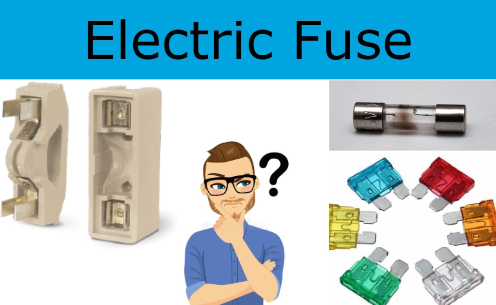
To avoid a short circuit or device failure, an electrical fuse is a low melting point copper or other metal wire that breaks due to heat-induced by Overcurrent or excessive load.

The flow of electric current warms up the items through which it passes. Electric water heaters, light bulbs, and irons are just a few examples of electric gadgets that make use of this phenomenon. It does, however, have certain downsides. For example, if this equipment becomes overheated, it may become damaged or even catch fire! In reality, the undesirable high electric currents harm not only these gadgets, but all of the appliances in our home.
What is an electric fuse | Fuse resistance | Functions

Any gadget can only withstand a certain quantity of electric current. If the current surpasses that limit, the device's components heat up, perhaps resulting in a fire! Is there a way to prevent this from happening? An "electric fuse" is a device that is used to prevent this from happening. It comes in a variety of forms and sizes. This is how it usually appears. It features a fuse wire that connects to the two terminals, both of which are constructed of metal. Zinc, copper, silver, or aluminum wire is used to make this wire.

The remainder of the switch is constructed of a non-combustible substance. It also makes great sense. We need to make certain that the gadget used to prevent fires in other devices does not catch fire! Now, how does it keep electrical gadgets in the home from catching fire? This fuse has now been installed in EVERY circuit in our house. The basic circuit will look like this. This simpler circuit has been shown in our films. So, when the electricity goes across the circuit, the fuse wire warms up. When there is a high current flowing through the circuit, the wire simply melts, resulting in a broken circuit! Yes, the circuit is broken, and no current reaches the device.

This is how an electric fuse works! Isn't it simple? You've probably seen one clear downside of electric fuses! The fuse wire cannot be reformed after it has melted. We must manually replace the fuse with the new one! Automatic fuses are currently employed to solve this problem. They are also known as "miniature circuit breakers," which are sometimes abbreviated as "MCB." They function similarly to automated switches. When there is an excess of current flowing in the circuit, they "turn off." This breaks the circuit and protects the appliances from excessive current. They also turn on automatically when the flow returns to normal!

Fuse's functions

A fuse is a service that provides useful electrical circuit over-current safety in the realm of electrical engineering. Some of the most important fuse functions are listed here.

  • Short-circuits are avoided by using a fuse.
  • Blackouts and overloading are prevented.
  • Between the human body and the electric circuit, it acts as a barrier.
  • Prevents damage from misaligned loads.
  • Prevents system failure caused by circuits that aren't working properly.
Comments

Popular posts from this blog

What is a Positive Temperature Coefficient (PTC) | Positive Temperature Coefficient Thermistor

PTC is an initial for Positive Temperature Coefficient PTC thermistors are resistors with a positive temperature coefficient, meaning their resistance rises as the temperature rises. PTC thermistors are classified into two types depending on the materials used, the structure of the device, and the production method. Solicitors are the earliest type of PTC thermistors, and they employ silicon as the semiconducting material. Because of their linear feature, they are employed as PTC temperature sensors.  The switching type PTC thermistor is the second category. The resistance-temperature curve of a switching type PTC thermistor is very nonlinear. When a switching type PTC thermistor is heated, the resistance initially decreases until a critical temperature is achieved. As the temperature rises above the critical point, the resistance rises substantially. This kind of PTC thermistor is commonly utilized in PTC heaters, sensors, and other applications. This second group includes polyme...

74HC165 Shift Register and your Arduino UNO

Today in this tutorial I'll explain to you how to control the 74HC165 parallel in serial out(PISO) shift register using your ARDUINO board. Here we used 74HC165 for increasing numbers of inputs of your ARDUINO board. Shift registers are often used for the purpose of saving pins on a microcontroller. Every microcontroller has a limited number of pins for general inputs and outputs (GPIO). Sometimes we have required more inputs and our controller does not provide such inputs at that time parallel in serial out(PISO) shift register is used to increase inputs. An 8-bit shift register needs 4 lines of a microcontroller. One pin to clock for data transfer, one for clock enable, one for shifting/loading/latching the bits, and one for serial data transfer. Here we used only 3 pins of microcontrollers. One pin for loading the bits, one pin to clock for data transfer, one pin to serial data transfer. In 74HC165 Clock enable pin is active low so we connect it to the ground. Two 74HC165 can be...

What is the Joule Thief Circuit and how does it work

A joule thief is a compact, low-cost, and easy-to-build self-oscillating voltage booster that is often used to drive small loads(3.3v 5mm LED). Other names for this circuit include blocking oscillator , joule ringer , and vampire torch . The circuit is a blocking oscillator variation that functions as an unregulated voltage boost converter. The output voltage is increased at the price of a larger input current draw, but the output integrated (average) current is reduced and the luminescence brightness is reduced. This joule thief Circuit uses a 1.2 V or 1.5 V single-cell electric battery to power LEDs. However, as the supply voltage reaches 3V, the LED begins to light. The theory of operation of a Joule thief circuit Joule Thief Circuit The joule thief circuit operates on a fairly basic basis. It operates by quickly switching the transistor. When the transistor is first switched off, a tiny amount of current flows via the resistor, primary winding, and base-emitter junction, assistin...