Industrial VS Commercial VS Residential Electrical Installation

Hey, in this article we are going to see the comparison between Industrial, Commercial, and Residential Electrical installation. We will make compare with respect to types, procedure, cost, safety, equipment, and many other essential factors. First of all, let's know what is electrical installation. Electrical installation is a procedure to install electrical circuits, wirings, equipment, and machines. The electrical installation can be divided into three major parts - 1. Installing of electrical equipment or device or machine 2. Make electrical connection or wiring for them 3. Provide them proper voltage and power to operate them. These different types of electrical installation required different types of electricians and management. For example, commercial electrical installation requires commercial electricians, industrial electrical installation requires industrial electricians, and residential electrical installation requires residential electricians. We already published an ...

How to Build Simple LED circuit | Calculate current limit Resistor

Circuit Design for LEDs. Discover how to create LED circuits. How to determine resistor size, how to protect LEDs, how long a battery will power a circuit, how to calculate resistor power rating, how to connect LEDs, and more. These are light-emitting diodes or LEDs. When a current is sent through one, light is produced. However, if we surpass its voltage and current limits, it will be destroyed immediately. The interior of the LED contains a small wire that can only withstand a particular amount of current.
How to Build Simple LED circuit | Calculate current limit Resistor

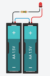
Assume you have a 3 volt supply and wish to attach a single red LED to it.

3v battery

What kind of resistor do we require?

How to Build Simple LED circuit | Calculate current limit Resistor

We know that this wire is 3 volts and that this wire is 0 volts. Because the led has a voltage loss of about 2 volts, our resistor must eliminate the remaining 3 volts. 
How to Build Simple LED circuit | Calculate current limit Resistor

To get 1 volt, subtract 2 volts. Because the led requires around 20 milliamps of current, 1 volt divided by 0.02 amps equals 50 ohms of resistance. For this computation, make sure you convert your milliamps to amps. We have a calculator on our website where you can just enter your data to make it easy. 

How to Build Simple LED circuit | Calculate current limit Resistor

Now go ahead and attempt to solve this one before I post your answers in the comments area below.

Example

Let's imagine we have a 9-volt battery and wish to attach a yellow led that consumes 20 milliamps of current and has a voltage drop of 2 volts.

How to Build Simple LED circuit | Calculate current limit Resistor

Current Limit Resistor Selection

How big of a resistor do you need? We have a 9-volt supply, so we deduct 2 volts for the led, leaving us with a 7-volt drop for the resistor. Because the current is 20 milliamps, the resistance is 350 ohms when 7 is divided by 0.02 amps. 

How to Build Simple LED circuit | Calculate current limit Resistor

The issue now is that we lack a 350-ohm resistor. Only 330 or 390 ohms are available. So, which should we go with? We must guarantee that the current does not exceed 20 milliamps, as we observed before.

To accomplish so, divide the needed voltage drop of 7 volts by the resistor value of 330 ohms to obtain 0.021 amps, then repeat for the 390-ohm resistor to obtain 0.018 amps. We may also combine resistors to obtain the exact value we want

led resistor calculator formula

To calculate the resistor value, we'll use the formula below: (Battery Voltage - LED Voltage) / desired LED current = resistor. The numbers are (12-3.4)/. 010=860 ohms for a standard white LED that uses 10mA and is supplied by 12V. Sum the current values to utilize many LEDs in parallel.

How to Build Simple LED circuit | Calculate current limit Resistor

Battery Backup Calculation

How long will this battery last in order to power our circuit? Let's pretend this battery has a 500 milliamp-hour rating. Simply divide this by the entire circuit current, which is 18 milliamps in this example. So we get roughly 27 hours if we split 500 milliamp hours by 18 milliamps.

Comments

Popular posts from this blog

What is the Joule Thief Circuit and how does it work

A joule thief is a compact, low-cost, and easy-to-build self-oscillating voltage booster that is often used to drive small loads(3.3v 5mm LED). Other names for this circuit include blocking oscillator , joule ringer , and vampire torch . The circuit is a blocking oscillator variation that functions as an unregulated voltage boost converter. The output voltage is increased at the price of a larger input current draw, but the output integrated (average) current is reduced and the luminescence brightness is reduced. This joule thief Circuit uses a 1.2 V or 1.5 V single-cell electric battery to power LEDs. However, as the supply voltage reaches 3V, the LED begins to light. The theory of operation of a Joule thief circuit Joule Thief Circuit The joule thief circuit operates on a fairly basic basis. It operates by quickly switching the transistor. When the transistor is first switched off, a tiny amount of current flows via the resistor, primary winding, and base-emitter junction, assistin...

What is an electric fuse | Fuse resistance | Functions

To avoid a short circuit or device failure, an electrical fuse is a low melting point copper or other metal wire that breaks due to heat-induced by Overcurrent or excessive load. The flow of electric current warms up the items through which it passes. Electric water heaters, light bulbs, and irons are just a few examples of electric gadgets that make use of this phenomenon. It does, however, have certain downsides. For example, if this equipment becomes overheated, it may become damaged or even catch fire! In reality, the undesirable high electric currents harm not only these gadgets, but all of the appliances in our home. Any gadget can only withstand a certain quantity of electric current. If the current surpasses that limit, the device's components heat up, perhaps resulting in a fire! Is there a way to prevent this from happening? An "electric fuse" is a device that is used to prevent this from happening. It comes in a variety of forms and sizes. This is how it usuall...

Using the IR2110 high-low side driver - explanation and circuit examples

In many situations, we need to use MOSFETs configured as high-side switches. Many a times we need to use MOSFETs configured as high-side and low-side switches. Such as in bridge circuits. In half-bridge circuits, we have 1 high-side MOSFET and 1 low-side MOSFET. In full-bridge circuits we have 2 high-side MOSFETs and 2 low-side MOSFETs. In such situations, there is a need to use high-side drive circuitry alongside low-side drive circuitry. The most common way of driving MOSFETs in such cases is to use high-low side MOSFET drivers. Undoubtedly, the most popular such driver chip is the IR2110. And in this article/tutorial, I will talk about the IR2110. Notice that the IR2110 comes in two packages – 14 pin through-hole PDIP package and the 16-pin surface mount SOIC package. Now let's talk about the different pins. VCC is the low-side supply and should be between 10V and 20V. VDD is the logic supply to the IR2110. It can be between +3V to +20V (with reference to VSS). The actual voltag...