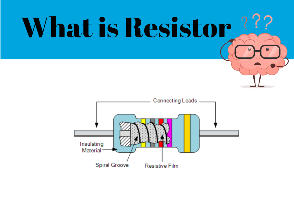
What is the definition of a resistor? This may be a decent definition. The standard symbols for resistors are given below zigzag on the left is the American standard and the one on the right is the international standard by the IEC to explain the definition more clearly we use the example of water flowing through a tube the flow of water is similar to the electrical current in an electrical circuit the pressure difference that causes the flow of water is similar to the pressure difference that causes the flow of electrical current in an electrical circuit.
The pressure difference that causes water to flow can be compared to the voltage difference that causes an electrical current to flow. If we create resistance in the flow of water, the current will decrease. We can do this for example by making the tube narrower at a certain point. A resistor is similar in that the resistor has a higher resistance than the connecting leads and causes a reduced electrical current.
Ohm's law is a law that describes resistance. Electrical resistance is equal to voltage divided by current, according to Mr. Ohm, a German physicist who discovered it in 1827. Resistance is measured in ohms, voltage is measured in volts, and current is measured in amps in this formula. This may be demonstrated with a simple circuit including a battery and a resistor. The current is restricted by the resistor, which is caused by the voltage source. What resistance do you have if the power source is 2 volts and the current is 4 amps? The resistance is equal to the voltage divided by the current, or 2 over 4 equals 0.5 ohms, according to Ohm's law. Let's say we wish to use a 9-volt battery to power a red LED. A maximum current of 30 milliamps is specified for the LED.
If we connect the battery directly to the LED, it may burn out quickly. We know that resistance equals voltage divided by current, or nine volts divided by 0.03 amps equals 300 ohms, according to Ohm's law. The LED emits light when the negative lead is connected and a circuit is formed. The most common form of the resistor is the fixed resistor, which has a constant resistance value. The majority of people use the term "resistor" to refer to a fixed resistor. A real carbon film resistor is shown in the illustration. Axial and SMD packaging are offered for fixed resistors. The resistance value of most variable resistors may be adjusted. When most variable resistors are set, they are modified by mechanical action.
When they're utilized as voltage dividers, they're called variable voltage dividers. Potentiometers are what they're called. Rheostats are variable resistance devices that are used to regulate the current in a circuit. Instead of being regulated mechanically, digital potentiometers are controlled electronically. Resistors go into a third type, with their resistance altering depending on a physical parameter such as light temperature or voltage. They're frequently employed as measuring instruments. Another classification of resistors is based on the resistance material and structure. Wound resistors are still used today for what reason? A resistive wire is wound around a non-conducting core to make them. They may have a very poor resolution.
They can have very low resistance values and are very easy to manufacture. Furthermore, they are quite long-lasting. The parasitic reactance for higher frequencies is a disadvantage. Non-conducting qur'anic and carbon particles are mixed together to make carbon composition resistors. They're also rather ancient, having been the most used resistor type a few decades ago. Despite the fact that their characteristics are inferior to autotypes in terms of tolerance, they are still fresh and intended for specific purposes. They can, for example, tolerate strong energy pulses without being damaged. In today's world, carbon film resistors are frequently utilized.
They're comprised of a non-conducting core surrounded by a thin carbon layer. Carbon film resistors are more accurate than carbon composition resistors, but they have poorer characteristics than metal or metal oxide film resistors. Metal film resistors have a similar structure to carbon film resistors, except instead of a carbon film, they feature a metal layer. They are more accurate, have a lower temperature coefficient, and are quite stable. Metal oxide film resistors are even more durable than metal film resistors, with greater temperature resistance and dependability. To show the resistance value and tolerance, most axial lead resistors include labeling with colored bands.
This resistor has four color bands and is made of carbon composition. The first band represents the resistance value's first digit, while the second band represents the value's second digit. The third band denotes a multiplication factor, while the fourth band reveals the resistor's tolerance. You might attempt to remember what each band and color means. You may also interpret the code at resistor guide calm using the resistor color code chart. You might even be able to discover an automated calculator that will decode the code for you. The first red band on the chart has a value of 2, while the second blue band has a value of 6. The third band is grey, indicating a 10,000-fold multiplication factor.
The fourth golden ring represents $1.5 percent. The resistor has a value of 2.6 mega ohms and a tolerance of 5%, as we know.

Comments
Post a Comment
if you have any doubt comment me I will try to resolve